Mp3 Speaker Manufacturing Process
The drawing above shows the model with a flange and also two cut outs. These had to be filled back in prior to machining and later cut by hand as the model was not considered strong enough to be held for machining with them in.
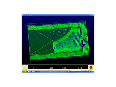
Decisions then had to be made as to which machining process to use. For the size of my product I chose to use the Unimatic CNC routing machine. The cutting process was simulated using the Boxford GeoCam software. This allowed me to see if there were any potential problems before machining commenced. Potential problems could have been the size of blank cut - either too small or too big, or that the depth of cut required for my product exceeded the depth of cut for the cutting tool.
 |
| Screen shot from the simulator software |
Having simulated the file it was then saved as a file specifically for the Unimatic CNC machine. Then it was a matter of clamping blank onto machine bed and lining the tool up to the back left-hand corner and making a note of the X,Y and Z co-ordinates. As my product was being manufactured in two halves, the process involved four lots of work machining each blank from each side to produce the hollowed out side and the outside profile.
 |
| Screen shot from the Unimatic CNC Machine showing the path the tool is taking during the cutting process |
Product being machined on the Unimatic CNC Router:
(Notice on the right hand half the tool ripped away the material in the wrong place. This would have to be filled in the finishing process.)
The finishing process included working through the grades of sanding to achieve a fine smooth finish for painting; cutting in the slots for access to the battery and for holding the Mp3 player during playback; and ensuring that all other components would fit prior to assembly. I added a battery holder made from pieces of acrylic. Holes were drilled in the model for the switch and to allow the input lead to come out. A removeable lid representing the aquatic centres "Wave roof "was cut from acrylic warmed in the oven and formed into the wave shape by moulding on top of the model. This was then secured by self tapping screws which can easily be removed to change a battery.
 |
| Model prior to painting. |
The model was then ready for painting so a plastic primer was applied followed by several layers of base primer. The top coat colour, a metallic silver, was chosen and sprayed leaving a very sleek shiny finish.
The speaker grille was manufactured using the FDM printer which is were the form is built up using melted polymer rather like cake icing.
I had made the speaker in such a way that all the electronic components could be soldered outside of the model and then fitted. The roof lid and speaker grille were then attached.


